The Construction of Space Shuttle Launch Complex 39-B
A very personal and technical written and photographic history, by James MacLaren.
Tracking the Steel: Page 2 - HFL 161-209.
| Pad B Stories - Table of Contents |
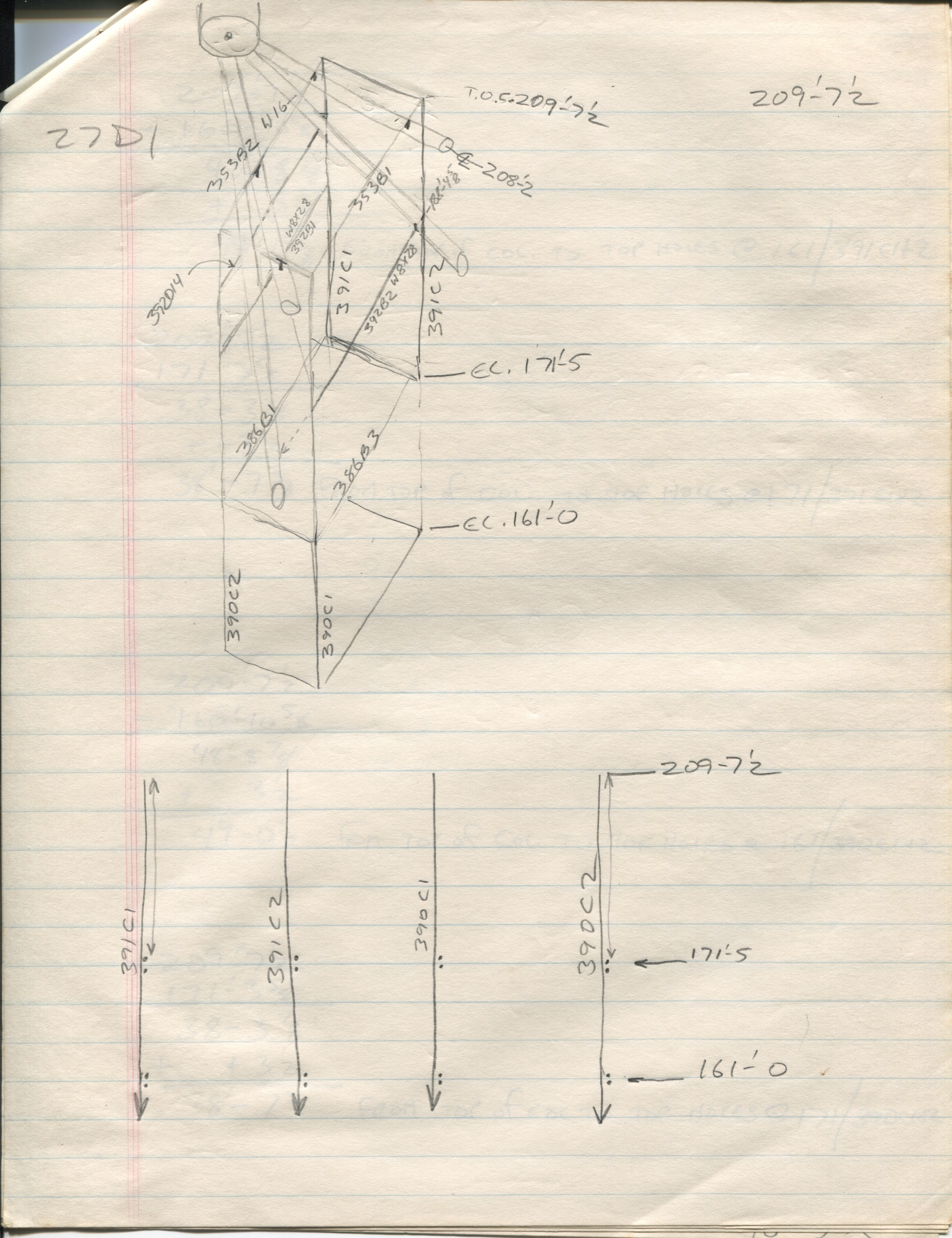
We're looking across and down at the RSS from above and behind, with the upper Hinge Column Bearing going off the top of the page, top left.
This is a difficult area to visualize, and I'm quite sure I created this isometric view to help me make a little more sense of things, in an area where you have square beams and hangers, intersecting and connecting with round pipes, that angle and slope away from the Upper Hinge Column Bearing in four different directions.
Although it never occurred to me at the time, I can now easily imagine Dick Walls sitting at his desk after handing this one to me, chuckling silently to himself and thinking, "Ok, let's see if Mister Hotshot can make any sense out of this one." I've got a feeling I was being tested, and was just too stupid to realize it.
And it's looking like there were questions about how the Hanger Frame was sitting down on top of the RSS Primary Framing structural pipes up at 208'-2", as well as further curiosity about bolt-holes at the next two framing levels down.
Alas, I have no trustworthy recollection of creating this sketch, nor why it was done, and from here on, I'm flying blind, just guessing, based on what's included in this sketch.
First off, although it's not real easy to see, I bore down with the pencil pretty hard on those four places where the top rectangular frame appears to be resting on top of the RSS Primary Framing. Those items are noticeably darker that what surrounds them, and this is exactly the sort of thing I would do, to indicate special attention be paid to these places.
Those very small connections between the big Main Framing pipes at elevation 208'-2" and the W16 wide flange beams forming the rectangular hanger support frame that sits on top of them...
 ...appear to be our main items of interest here.
On the far left side, up at the top of this sketch, "27D1" can be seen, and that's Dick Wall's handwriting, not mine, and the low drawing number "27" makes me think it would be referring to a primary framing member, one of the big pipes, and we've got four separate pieces of it here, two on Line B, and two extending between Line B and Line A.
That said, pretty much everything in the sketch has piecemarks, except the Primary Framing, so... I dunno.
Let's go find those connections. Maybe there'll be something there for us.
S-23 is the contract drawing for the Top Truss, elevation 208'-2" so we'll go there first and see if there's anything there we can work with.
Nope. Nothing. Well... except for the fact that it's telling us that we're dealing with a pair of 24" Ø pipes up here at 208'-2" between Column Lines 1 and 2 which is the area that we're interested in, and who knows, maybe that might come in handy later on. Dunno. One thing I do know is that structural pipe is measured using its outside diameter, and as the pipe gets heavier, it's the inside diameter that changes, as the wall-thickness of the pipe increases with the increasing weight of the pipe. Up in this area, we have two differing pipes, one a 24 Ø x 246, and the other a 24 Ø x 231, and both of them are exactly 24 inches in outside diameter, which means that it's exactly one foot from their centerlines at elevation 208'-2" to their tops, their bottoms, their... wherevers, and one exact foot is a nice easy dimension to work with, should we wind up having to work with it at some point later on.
And also, before we go any farther, my full field sketch makes three separate references to a very specific elevation, 209'-7½" and that one is a weirdie, and I don't think I've ever seen it anywhere on any of the contract drawings, and it's very much looking like (down in the bottom half of the field sketch) it's somehow tied in with whatever questions there might be about bolt-holes, at elevation 171'-5" which is a "normal" elevation, and again, farther down the hanger at elevation 161'-0" which is also a "normal" elevation.
And the part of the sketch down below with the four Hangers in it, 391C1, 391C2, 390C1, and 390C2 (and yeah, they piecemarked 'em on the detail drawing as 'C' like they were columns, and yeah, sometimes they do that, and you just have to be on your toes about this stuff at all times) is very specifically referring to that weirdie 209'-7½" elevation, and up at the top of the sketch, it even has "T.O.S." in front of that elevation, and that's very much standard nomenclature and it stands for Top Of Steel, and it's the standard way things get measured when they're not getting measured to centerlines or workpoints, so it's looking like we were trying to get to the bottom of things with the exact locations of those bolt holes, the top sets of which on hangers 390C2 and 391C1 even have dimension arrows pointing to them, without any dimension being given.
So. We're playing Fill In The Blank here, it would appear.
What's really going on here, anyway?
This is the stuff that holds up a bunch of the Crossover Platforms, so let's go to S-81 RSS Crossovers Plans, and see what's there.
Ok, now it's looking like we're on to a little something.
They're referring to it as the "Roof Framing Plan Top Of Steel 211'-0" as if we were working on the RSS Roof, but the RSS doesn't have any roof over here and the whole place is wide open up on top. Open framing. No roof. None at all. You get a catwalk farther up, at 220' but no roof.
Despite the fact that it's deviously-mislabeled, there's some pretty good info in here.
It's poorly-presented info, but it's good info. The drawing itself isn't good at all, though. The drawing is bad, and with a drawing like this, I can see where there were questions.
Another bit of weirdness is that our hangers have individual numbers on the contract drawings, and that's very unusual, and no, I have no idea what that one's about, nor do I have any idea if it will enter in to things before we're done here. Just one more bit of strangeness, in an already plenty-strange-enough drawing, as it is.
We're getting confirmation that the beams in my sketch are W16's (W16x40 to be precise) and they really are sitting on top of the Main Framing, and also extend past it a little bit (by 1'-9" to be precise) on the Line B side, extending past the centerline of Line B, but the note indicating that's the case is pointing to the one connection we don't care about, and doesn't even bother to take any arrows to the other, similar connections which are indicated "Post Down to 24" Ø Typ 5 Places See Sht. S30" and you just sort of have to figure out which ones are which, and once again, bad drawing.
Somebody was in a hurry. Somebody went over budget and was breathing down somebody else's neck to hurry up and get done, and this drawing suffered. Either that, or they put somebody on it who was less than fully-wonderful, and whoever checked the work and gave it a pass was none too wonderful, either. I dunno. But I'm starting to see a pattern with this kind of stuff here, and yeah, I can well imagine that Dick Walls, or Sheffield Steel, or Wilhoit, or somebody was having their doubts about this stuff, and wasn't all-the-way happy with what they were getting off of this drawing. And yeah, that happens, too. More than you might imagine. Definitely more than you'd like, especially if it's you that's having to build the damn thing, using drawings like this one.
And oh by the way, what's the difference between Roof Framing T.O.S. 211'-0" and our infamous 209'-7½"?
Lessee here...
210-12
-209-7½
1-4½ which equals 16 and a half inches.
Ok, what's a W16x40 worth?
Goes and digs out steel book.
16 inches exactly.
Which puts our weirdie 209'-7½" T.O.S. one half inch from being the depth of those W16x40's away from 211'-0"
And that's not quite close enough, but it's too close.
Ok, they're telling us "Post Down to 24" Ø Typ 5 Places See Sht. S30", so let's go look at S-30 and see what it might have to say about things.
And you get this. And once again, bad drawing, because this is not precisely what we're dealing with up at T.O.S. 211'-0" and it's definitely not showing a wide-flange beam sitting on top of the little pipe-stub support.
But it's telling us that our little connection pipe stub is supposed to be six inches tall, and if you come up from the centerline of the Main Framing pipe at 208'-2" one foot for half the diameter of that pipe, and another six inches per Typical Post Detail A, you wind up at elevation 209'-8" which is exactly the same elevation you'd get if you came down sixteen inches from the given level of the W16's shown on Roof Framing T.O.S. 211'-0" so at this point I have no idea what's going on with that Mystery 209'-7½" elevation, or the bolt-holes on those hangers, down below it, nor do I have any further real idea what's going on with this whole field sketch.
Were "columns" 390C2 and 391C1 misfabricated, one-half inch too short, possibly mislocating the elevations of their sets of bolt holes? Are the 79K14110 drawings I'm working with right now altered in some way. There's certainly more than enough other things sprinkled around all over the place that disagree, strongly, with what was being fabricated and erected at the time because some subsequent modification or other came along, causing significant changes to things, elevations included. But this stuff, the W16's are also holding up the Crossover Catwalk from FSS elevation 220'-0" and there's no mention anywhere about that, so... probably not, right? So what the hell is it?
It's been too long. Forty years too long. I simply do not know.
And at this point I'm going to just have to close the conversation and leave this one filed under "Unknown" and, reluctantly, move on along to our next and final field sketch.
However incomplete and unsatisfying any of the foregoing may be, this whole little saga does illustrate quite well, the sorts of things you go through on a daily basis, as questions come up from various parties, and you find yourself chasing through the contract drawings, and sometimes you get an answer, and sometimes you don't, and when you do, you proceed with the work, as-shown, and when you don't, you send an RFI (Request For Information) up the chain of command, and that's a whole separate chapter (and a long one at that), and we'll be getting our feet good and wet in that grievously-muddy water soon enough, but not right now, ok?
Return to 16streets.comACRONYMS LOOK-UP PAGEContact Email Link |